Sensor cleaning, Panasonic Lumix FS18
Published: 28 April 2017
Contents
Introduction
Compact cameras have a disadvantage compared with DSLRs that getting to the sensor to clean 'dust' off it requires dismantling the camera. And dust, sticky dust, probably pollen, always gets there eventually.
Professional cleaning costs sometimes as much as the camera is worth in second hand value at least. So a DIY clean is worth while, especially if the dust is so intrusive that you consider replacing an otherwise perfectly good camera with a new one.
The Panasonic Lumix FS18 was one of the smaller cameras in the Panasonic Lumix range and is probably very similar in construction to other models in the FS series, although this has not been checked. It is quite easy, if tedious, to dismantle, with no real snags, and I have done it a few times on my model.
Tools
You will need a Phillips size 000 cross-head screwdriver, a lens puffer cleaner, and cotton wool buds. Also a strong light (to see by) and ideally a fairly strong magnifying glass to inspect closely for dust. And containers to place bits in, especially screws, so they don't get lost or muddled. I have used plastic containers from an Indian takeaway. (Washed of course!) If you have trouble handling tiny screws in replacing them, suitable tweezers may help. I didn't bother.
Very cheap (Poundland style) instrument screwdriver kits are useless for the smaller sizes, the shaping of the business end is crude and you will mess up the screws without extracting them. I got a kit in a small wallet from Maplin, for £5.99 (in 2012), which is very satisfactory - product code N46FB on the receipt. Size 000 is the smallest in the kit, but they are marked on the shank if in doubt.
Venue
Ideally a kitchen with good lighting and a clean flat floor. Nowhere with a carpet or gaps in the floorboards, it is just asking for the tiny screws to be lost. For similar reasons it is best to work over a large rimmed tray.
Off we go
Remove battery and probably best to remove SD card as well.
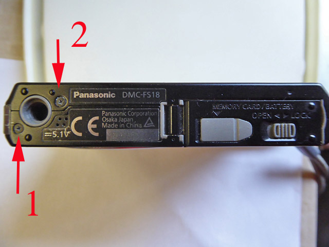
The camera casing is split into a front bit and a back bit. We need to remove the back only, so the screws for this need to be removed, plus one apparently, from the outside, for the front also. Start at the bottom with screws 1 and 2. and place them somewhere with e.g. a note on a scrap of paper so they can be identified. Screws are the same diameter but not all the same length.
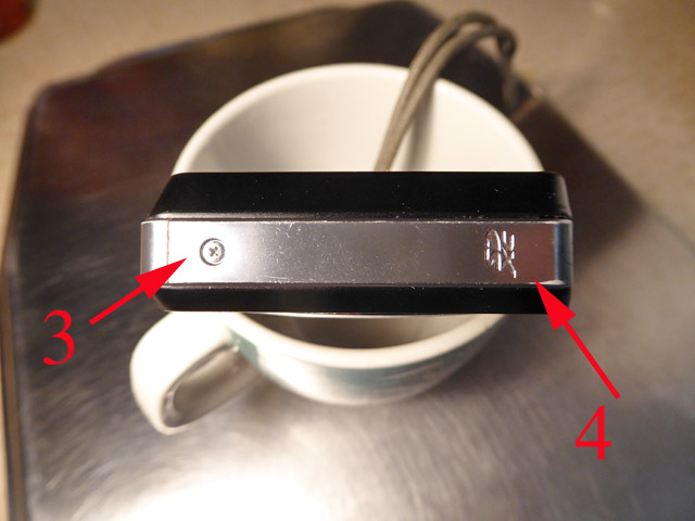
Then screw 3 at the 'silver end', and remove the silver end plate, lifting first at end 4 using fingernail or small flat bladed screwdriver to start. The end local to screw 3 is hooked under so won't lift directly.
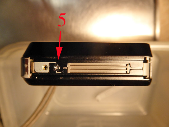
This reveals screw 5 which needs to be removed.
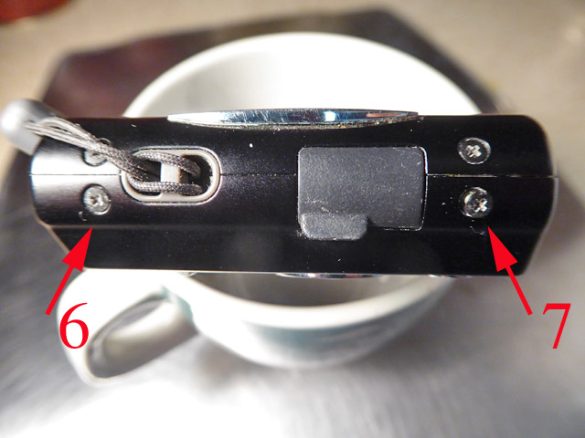
Now go to the other end and remove the final casing screws 6 and 7.
The rear casing can now be lifted away, again perhaps using using fingernail or small flat bladed screwdriver to start.
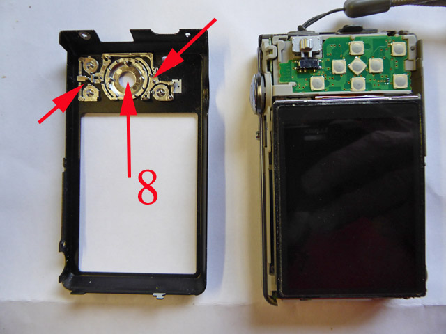
It is likely that the central 'Menu/Set' button on the rear controls will fall out, it is missing in this view (8). The unnumbered arrows show where its arms must be relocated on reassembly, making sure 'Menu/Set' on the other side is right way up and level. The location is not very positive, so during reassembly it is best to bring the rest of the camera down onto the casing so it does not fall out again.
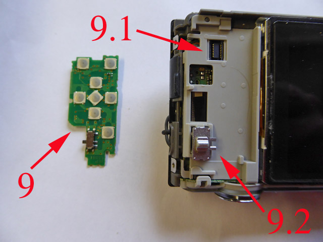
This is the point where I gave up the first time I attempted this, as I couldn't see how to get the screen out of the way. On my TZ8 and TZ19 you don't remove circuit boards, but it turns out that on this model you do. The green board (9) is lifted out. The only resistance should be unplugging the plug from the socket (9.1) on its underside. A reassembly note - at 9.2 move the external slide if required to engage properly with the actual switch on the board.
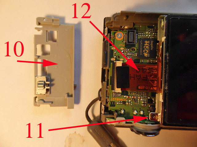
Now remove the grey plastic mount 10, located on a spigot or two so should just lift out. This reveals that the screen is attached by a ribbon cable 12, which is left, and the vital screw 11, which is removed.
The screen can now be lifted aside, but remaining attached by its ribbon cable, gently using the cable as a hinge. We see that the rear of the screen has a mirror finish, my hand taking the photo and a desktop light are visible. We also see a grey steel plate that was under the screen.
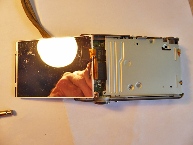
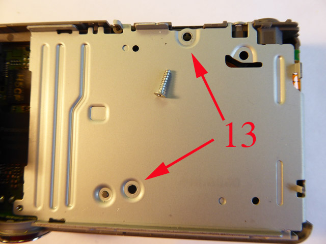
The steel plate has to come out, remove two screws at 13 (already removed in view, one is visible) and lift the plate away.
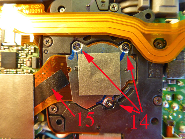
We are now getting to the heart of the matter. Revealed is the sensor assembly, attached by a ribbon cable 15 and three screws 14.
Remove the screws and gently hinge back the unit on its ribbon cable. It will be springy, so needs to be held back for the cleaning operation. We can now see the back of the lens assembly 16 and front of the infra-red filter 17. The filter is in front of the sensor but no further dismantling is required, as the possibility of dust getting between filter and sensor is remote.
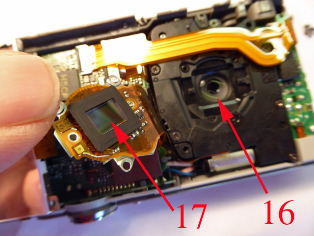
It is undesirable to take too long from now on, as the surfaces you want to be be clean are now exposed to all the dust floating around in the air - and there is a lot. First clean the back of the lens 16 with a cotton wool bud and puffer. Not vital, but since it is now exposed we might as well take the opportunity. Then do the same with the IR filter surface 17, where all your problems are. Just a puffer is not good enough, so gently wipe with a cotton wool bud. Inspect with magnifying glass, angling the lighting in various ways to detect any remaining or newly introduced dust. The tiniest particle will loom large in the photo. I must admit I skipped this bit for the purposes of this article, so whilst I removed the nine specks I had detected on photos (particularly on telephoto settings), I introduced one speck in a new place.
No photos for the actual cleaning as I don't have enough hands!
Reassembly
Without discipline this is often harder than dismantling, but if the sequence above is followed in reverse order, and the screws have been identified and not muddled up, all should go fine.
There are some particular points:
1. When reseating the sensor assembly, screws 14 should be gradually tightened going round in sequence, car cylinder head fashion, not each fully tightened before going to the next.
2. When reseating the circuit board 9, take note of remark about switch 9.2.
3. Note remarks about button 8.
4. Put screw 5 in correct hole. I have put it in the wrong hole in the past and wondered why screw 3 wouldn't go anywhere.
![Creative Commons Licence [Some Rights Reserved]](https://s1.geograph.org.uk/img/somerights20.gif)
